
The COMTECH 23Cms Receiver
Click
here to Bookmark this site (Not available in Chrome)
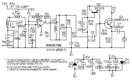
The Comtech has become the de facto standard now for those entering the Amateur TV scene . Sadly the production may be coming to an end with the lower demand for analog tuners and the ICs used becoming obsolete.With the demise of the G1MFG website there is only a limited amount of information about modifying and upgrading these useful workhorses. I have attempted to collect together the most useful information and links to make it easier for you to source the details you need. Remember that the Comtec modules have to have correct pre and de- emphasis added, the on-board C/R hf lift filter next to the preset are non standard and should be by-passed. A regular pre-emphasis to CCIR 405 standard should be used.I recommend removing the original filter components on the receiver board and fitting CCIR405 de-emphasis to the receiver but extra gain will be needed afterwards to raise the video level to 1volt pk to drive monitors etc. The original common base addon board used on the MFG boards suffered from field crushing and generally poor sync handling. A revised version using a simple emitter follower instead is shown below and can be fitted onto the original add-on board. There are a few different versions of the board with the latest ones having a dual audio chip and switching regulator IC, but otherwise the layout is very similar. The NE592 is a high gain video amp that was designed for dvd laser output amplification . The built in non-linearity and sharp drop in bandwidth at higher gains means that it is working at full stretch trying to overcome the losses of the de-emphasis circuit.
Where to buy Comtech equipment.
www.13cm.co.uk
www.mobiComm.net(Ebay shop)
G8CKN Please enquire
Wimo(Germany)
If you know of other sources please tell me.
SWITCHES
|
|||||||||
| Freq | 1 | 2 | 3 | 4 | 5 | 6 | 7 | 8 | |
| 1249 | 0 | 1 | 0 | 0 | 1 | 0 | 0 | 0 | |
| 1255 | 0 | 1 | 1 | 1 | 1 | 0 | 0 | 0 | |
| 1258 | 0 | 0 | 1 | 0 | 0 | 1 | 0 | 0 | |
| 1260 | 0 | 0 | 0 | 1 | 0 | 1 | 0 | 0 | |
| 1308 | 0 | 0 | 0 | 1 | 0 | 0 | 0 | 1 | |
| 1311 | 1 | 1 | 1 | 1 | 0 | 0 | 0 | 1 | |
| 1316 | 0 | 0 | 0 | 1 | 1 | 0 | 0 | 1 | |
Some useful switch settings for the G1MFG / Comtech 23cm rx and tx boards.Full list here.As these settings are decided by the software used in the pic chip each supplier can choose his own settings.
For 13cm.co.uk version use inverted settings e.g.1249 is 10110111
Switch 1 is next to the led. 1=on 0=off
Note: If using 0.25Mhz steps see this Mobicom pdf.
see VE6ATV website for details.
Bridge the 3 capacitors shown and bypass the old pre-emphasis components by the preset pot.
Single Stage Audio Amplifier
The audio level from the Comtech is rather low for most uses so a simple line amp like this one will give sufficient boost to feed a monitor audio stage. It will run from the 9 volt regulator but with reduced gain.I use the 12v input dc, the circuit will work ok up to 16 volts if desired. I cut the centre pin of the audio output socket on the Comtech and fitted the circuit either side of the break.
DK Comments:
I have incorporated the above mods into my gear. There is no question in my mind that there are visible improvements to be gained by the transmitter mods. Not just getting rid of the poor l.f. response, but improving the contrast range, and really losing that 'fm' video look and giving a picture as good as commercial off-air pictures, especially if a proper black level clamp (BLC) is included. I believe that the mods to the transmitter are essential, even if you have not done the rx mods, but the capacitor and the resistor (simple pre-emphasis) feeding the drive level preset should be removed and a link inserted instead. This helps by improving the syncs and reducing the hf peaking (assuming proper pre-emphasis is being used e;sewhere).
The receiver mods. If fitted, the mod resistor onto the pin of the TA8804 inside the can should be removed and the filter components really need to be changed to the standard CCIR de-emphasis circuit which will mean an extra amplifying stage with a BLC to compensate for the attenuation, to ensure compatability with other ATVers. I have been working on a small board (see below) that will fit on the top of the tuner can and replace the video circuits entirely .
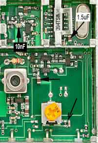
On the transmitter module the 1.5uF capacitor is best managed by bridging the existing cap with a 0.47uF 0805 SMD (i.e. same size as the 1uF original). The pre-emphasis components to the right of the preset should be shorted out. I have found that some frame droop can be caused by increasing the 1uF, and I feel that it is best left as 1uF for most signals. The 10nF is easier to fit if laid on top of the 35pF capacitor.
If after doing the tx mods you get no sound, check that the tiny 39k resistor is not displaced and that there is not a bridge between it and the small cap to its side after soldering in the .01mfd cap. A pulsing picture (on and off of frequency with some modulation) probably will be a solder bridge from the 220k resistor to a through connection just to its side (left side in photo above).
One (new) receiver was rather 'speckly' and appeared slightly low gain, the quadrature coil (4 turns green enamel wire, just visible below the A in signal strength meter picture) needed a nudge(less than 0.5mm to the right on the right hand half of coil, this centred the signal nicely.
Once again thanks are due to VE6ATV and please ensure you visit his website for full details and any further updates.
If you have any hints or further mods let me know and I will pass them on for others to see.
Use the 1k preset inside the Comtech can to set max deviation. Sadly,no supplier is currently stocking the MAX7450. Contact Maxim UK for samples/ordering details. Click on circuit for full pdf.Take pin 7 to ground to change from +6dB gain to 0dB. If you prefer not to have a negative supply, there is the MAX 7452.There will have to be a coupling capacitor >470mfd instead of R5.Connect the pad to ground instead of -5v. Pins 5 and 7 must be either +5 or ground not o/c . The pad under the ic must be connected to -ve to get an output.
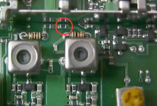
Place a 10nF capacitor with a 4k7 in series across the 47k resistor (in red ring).
Do the same if required for the second sound channel across resistor to the left of the red circle. SMD 0805 components will just fit in the space.If the 6.5Mhz is not required lift one leg of the left hand 1k to stop the carrier being used.It will save a little bandwidth and power. Picture: G1MFG
Available from 13cm.co.uk
In response to requests from a number of Amateurs, I have modified the above circuit
to add a simple clamp and amplifier to replace the unobtainable MAX7450 .
If you need a smd layout , click on this diagram for a pdf. .
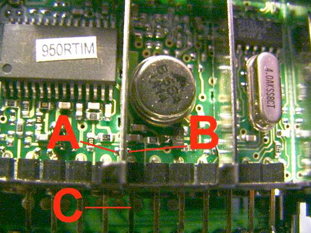
Place a link wire between points A&B take the feed out on pin C

 Use the address below the menu for emailing me.