|

DIGITAL
ATV RECEIVERS
COMAG
PORTY / SL55
MANHATTAN PLAZA
BIG SAT
INT'L
NDS CSR820
SL100HD
STARSAT
 CHOOSING A RECEIVER FOR DIGITAL ATV
Most Free-To-Air DVS (satellite tv) receivers are useable provided
they are capable of demodulating digital signal rates as low as 4
Ms/s. Terrestrial DVT and SKY boxes are not suitable for ATV.
CHOOSING A RECEIVER FOR USE IN A REPEATER
If you are looking for a Repeater input receiver you will need to
find one capable of giving a 'valid signal' detect line. The
reason that you cannot simply use a sync detector is that there is
a caption generated when the signal drops out and this generates
syncs , meaning that it is impossible to differentiate between the
signal and the caption.
The elderly SL55/56 has proved ideal. For use in a repeater the
Porty has a few disadvantages especially when handling signals
from modern encoders. Not surprisingly as it is a rather old model
now. The NDS makes a good home receiver but as it is designed to
be tuned to a fixed transponder in a rack mounted system it will
need to be retuned to accept different signals, making it
unsuitable for repeater use. The new BigSAT seems an excellent
replacement for well under £40 but it appears to suffer from audio
channel firmware errors that could be a problem for a repeater.
Following considerable research there is now an option to use the
Comag SL100 receiver by adding a small circuit to create a
lock-light type signal.Details below.The Plaza has a built in lock
light, we are currently assessing the receiver and will report
here later.
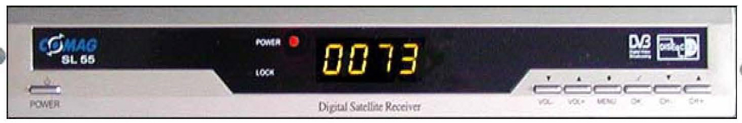
The Comag Porty is a low cost Free-to-Air
satellite receiver, the mains-only Porty and the mains or 12v
SL55. Almost identical but the SL55 has a useful 'lock' light
feature that enables a transistor to be added to control other
equipment such as a repeater changeover or a recording device to
be triggered. Remote controls are identical for both models but
are in short supply. The same unit is often rebadged as
Silvercrest and other names so most univeral remote controls
have the codes in them. I have placed what information I do have
(no circuits have ever been seen) on this page and a number of
links that might be of interest to you. A copy of the
instruction book is here.
Manual tuning of a repeater signal method
(actually for GB3SQ reception but relevant for others) is here.
To prevent the
on-screen message ' there is an lnb
short-circuit' appearing when the dc line to
the tuner and aerial socket is either open or short
circuit, lift the collector(centre)lead of smd
transistor QL3 (just in front of regulator heatsink)
and cut the dc line to the tuner by slicing the
track just above RT3 (SL55) or CT5 (Porty) with a
knife. Dont worry about cutting the thin ground
track alongside the edge of the board as it is not
needed. (SL55 layout shown)
What to do if your receiver has no lock
light
Receivers using the Sharp tuner can get a
signal from the tuner itself that can be used to trigger other
circuits.
Pin numbers may vary with different versions, on the
early ones it was pin 1. Check with a voltmeter on an on/off
signal. This will work on any incoming, either digital or analog
signal.
TRIGGER ON A VALID
SIGNAL
Using a sync detector circuit such as the LM567
on the analog receiver to indicate a valid digital signal cannot
be used here as the digital receivers display a 'No signal
found' OSG which generates syncs internally and the detector
circuit cannot distinguish between this and the received syncs.
Thankfully the processor chip does have a detector circuit that
is used to light up the front panel lock LED.
If you are using the SL55, which features a
LOCK light, you can use the voltage across the LED to trigger
the repeater (or recorder or whatever).
Using a digital switch FDV301N (or a NPN transistor) this
circuit can trigger a TTL level or PIC chip input port, use a
following stage to invert to positive on a valid signal if
preffered.The Porty has a pick up point on the pcb near the
processor chip that can be used, but the lock light is not
fitted.The later version Porty 2 has a 'lock' solder pad near
the tuner can.
Fitting a Lock Light on the BigSat
Receiver. Designed by G8DRK
Big SAT Int.
Adding lock light switch output to the
German Big Sat International receiver. The card reader should
be unplugged and removed to allow space for mods board.
In the photo you can see the red wire coming from the 5v
supply line at D108 or the nearby pad for R71 (not fitted).
CIRCUIT DESCRIPTION by Robin G8DRK
TR1 base and emitter are connected across the
Lock-LED, so TR1 can only turn on when the LED does.
Therefore all invalid strobing pulses (the
ones to light the channel display segments) are ignored.
R1 just limits current into TR1 base so the LED is not visibly
dimmed. On each valid pulse (the ones we're
interested in) the strobing chip pulls the LED anode high
(along with TR1 base) and, simultaneously, its cathode is
pulled down to chassis - and with it, TR1 emitter. This allows
TR1 to turn hard on, rapidly charging C1 to 5 volts.
This voltage across C1 enables R3 to feed current into
TR2 base. TR2 now turns hard on, delivering a 5
volts "high" across the pull-down resistor R4.
Between each strobe pulse, the voltage on C1 will fall a
little, but not enough to prevent TR2 from remaining
fully saturated. So no strobing pulses appear on its
output, just a constant 5 volts. R5 limits the available
current, preventing damage to TR2 or the 5-volt supply if the
output lead is shorted.
When the LED goes out (stops pulsing), C1 is no longer
being "topped up" via TR1. C1
discharges via R3 and TR2 base/emitter until, at
around 0.7 volts, TR2 starts to turn off.
R2 completes the discharge, sharpening the switch-off
characteristic. With TR2 off, the output drops to 0
volts. The channel display is still lit so there will
still be pulses appearing on TR1 base and its emitter, but
if both are pulsed high together, both low together, or base
low with emitter high, the transistor
remains off. Only pulses intended for the Lock-LED
(simultaneous base high and emitter low) will
forward-bias TR1 and "wake the circuit up".
In the photo the 47k resistor goes to the left-hand led pin
.This board was supplied by Robin.

I use the output directly onto a serial to USB converter to
trigger the FileStart program to begin streaming to the BATC
site when a signal is received from the local repeater, GB3SQ on
1304 MHz
 
|


